Thin-wall bearings, also known as thin section bearings, represent a specialized category of rolling bearings designed to deliver standard bearing performance within an extremely compact, lightweight footprint. Unlike conventional bearings where the cross-sectional height is proportionally large relative to the bore, thin-wall bearings feature a dramatically reduced cross-section relative to their bore diameter. This unique geometry makes them indispensable in applications where space and weight savings are critical — from robotics and medical imaging equipment to aerospace systems and precision automation. In this guide, we’ll explore the structure, working principle, key features, common configurations, selection criteria, and typical applications of thin-wall bearings.
What Is a Thin-Wall Bearing?
A thin-wall bearing is a rolling bearing characterized by a very thin cross-section relative to its bore size. While a standard deep groove ball bearing might have a cross-sectional height that scales noticeably with bore diameter, a thin-wall bearing maintains a nearly constant or minimally increasing cross-section even as bore diameter grows significantly. This means a thin-wall bearing with a large bore can have almost the same cross-sectional thickness as a much smaller standard bearing.
This design philosophy allows engineers to integrate bearings directly into structural components — such as robotic joints, rotary tables, or instrument housings — without the bulk and weight typically associated with conventional bearing assemblies and their housings.
Structure and Components
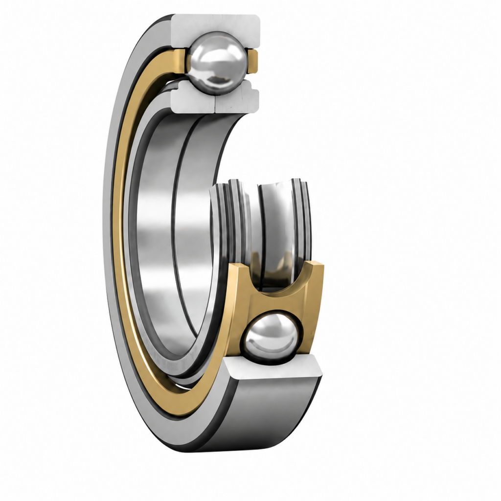
Thin-wall bearings generally share the same fundamental components as standard rolling bearings, but with a refined, compact geometry:
- Inner Ring – Thin-walled, often designed for direct mounting onto a shaft or structural component.
- Outer Ring – Also thin-walled, frequently bolted directly into a housing or frame without additional fitting hardware.
- Rolling Elements – Depending on the design, these may be balls (in deep groove, angular contact, or four-point contact types) or crossed rollers (in cross roller designs).
- Cage (Retainer) – Maintains even spacing of rolling elements, often made from lightweight materials to further reduce weight.
Because thin-wall bearings are frequently designed for direct integration, mounting holes are often machined directly into the inner and outer rings, allowing the bearing to be bolted straight into a structure — eliminating the need for separate housings or shaft collars.
Working Principle
The working principle of thin-wall bearings is fundamentally the same as that of standard rolling bearings: rolling elements reduce friction between the inner and outer rings, allowing smooth relative rotation. What differs is the geometric ratio between cross-sectional height and bore diameter, often referred to as the section ratio.
A lower section ratio (thinner cross-section relative to bore) means:
- Reduced Weight and Volume – Less material is used, dramatically cutting bearing mass.
- Compact Integration – The bearing can be embedded directly into housings, reducing overall assembly size.
- Trade-off in Rigidity – Thinner cross-sections generally provide lower stiffness and load capacity compared to standard-proportion bearings of the same bore size, requiring careful selection based on actual load requirements.
This trade-off between compactness and rigidity is the defining engineering consideration when working with thin-wall bearings.
Key Features and Advantages
- Extreme Weight Savings – Significantly lighter than standard bearings of equivalent bore size, critical for weight-sensitive applications like aerospace and robotics.
- Space Efficiency – Compact cross-section allows for tighter overall system packaging.
- Direct Mounting Capability – Pre-machined mounting holes enable installation directly into structural components, simplifying design and reducing part count.
- Multi-Directional Load Capacity (Cross Roller Types) – Crossed roller configurations can simultaneously support radial loads, axial loads in both directions, and moment (tilting) loads — all in a single bearing.
- High Precision – Often manufactured to tight tolerances, suitable for precision rotary applications such as indexing tables and robotic joints.
Common Types and Configurations
Thin-wall bearings come in several standard configurations, each suited to different load profiles:
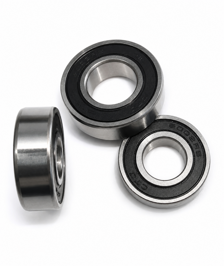
- Type R (Radial/Deep Groove Type) – Similar in principle to a deep groove ball bearing but in thin-section form; supports primarily radial loads with light axial capability.
- Type A (Angular Contact Type) – Balls contact the raceways at an angle, providing improved axial load capacity in one or both directions depending on configuration.
- Type X (Four-Point Contact Type) – A single row of balls makes contact at four points with the raceways, allowing the bearing to support radial loads and bidirectional axial loads in a single, compact row.
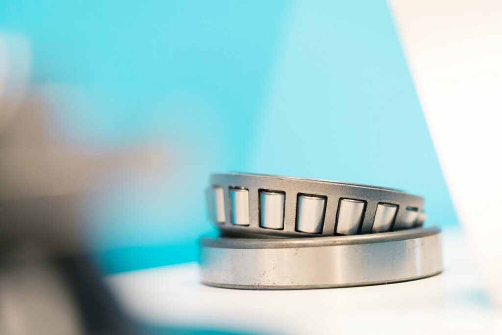
- Crossed Roller Type – Cylindrical rollers are arranged perpendicular to each other in alternating fashion within a single track. This configuration offers exceptional rigidity and can handle radial, axial, and moment loads simultaneously, making it ideal for rotary tables and robotic joints subject to combined loading.
Common Designations, Sizes, and Materials
Thin-wall bearings are typically specified using bore diameter, outer diameter, and cross-sectional height (rather than the “width” terminology common in standard bearings), since the relationship between these dimensions is the defining characteristic of the product line. Many manufacturers use proprietary series designations (such as KF, KA, KB, or similar codes), so cross-referencing manufacturer catalogs is often necessary when specifying a replacement.
Common materials include:
- Chrome Steel – Standard choice, offering a good balance of hardness, fatigue resistance, and cost.
- Stainless Steel – Used in corrosion-prone or cleanroom environments, such as medical and semiconductor equipment.
- Lightweight Cage Materials – Plastics or aluminum alloys are sometimes used for cages to further reduce overall bearing weight.
How to Select the Right Thin-Wall Bearing
Selecting the appropriate thin-wall bearing requires careful evaluation of several factors:
- Available Space – Determine the maximum allowable bore, outer diameter, and cross-sectional height for your application.
- Load Type and Direction – Identify whether the application involves purely radial loads, axial loads, or combined moment loading; this will determine whether a Type R, Type A, Type X, or crossed roller design is appropriate.
- Rigidity Requirements – Applications requiring high positioning accuracy (such as robotic joints or rotary tables) often benefit from crossed roller designs due to their superior stiffness.
- Mounting Method – Confirm whether direct bolt-in mounting (using pre-drilled holes in the rings) suits your structural design, or whether a separate housing is preferred.
- Precision Class – High-precision applications, such as semiconductor handling equipment, require tighter tolerance classes than general industrial use.
- Environmental Conditions – Consider exposure to contaminants, temperature extremes, or cleanroom requirements when selecting materials and sealing options.
Typical Applications
Thin-wall bearings are widely used in applications where space and weight constraints are paramount:
- Robotics – Robotic arm joints and rotary axes, where compact size and combined load capacity are essential.
- Medical Equipment – Rotating components in CT scanners, MRI machines, and other imaging equipment requiring precise, smooth rotation within tight enclosures.
- Semiconductor and Precision Instruments – Wafer handling systems and precision measurement equipment requiring high accuracy in confined spaces.
- Aerospace – Small turntables, antenna positioning systems, and satellite components where weight reduction is a top priority.
- Industrial Automation – Rotary tables, indexing units, and machine tool components requiring compact, high-precision rotation.
Thin-Wall Bearings vs. Standard Bearings
| Feature | Thin-Wall Bearing | Standard Deep Groove Ball Bearing | Standard Cross Roller Bearing |
|---|---|---|---|
| Cross-Section Relative to Bore | Very thin | Proportionally larger | Larger |
| Weight | Very low | Moderate | Higher |
| Direct Mounting | Yes (pre-drilled holes) | Typically requires housing | Sometimes |
| Combined Load Capacity (Cross Roller) | Excellent | Limited | Excellent |
| Common Use | Space/weight-constrained precision applications | General purpose | Heavy-duty rotary tables |
Conclusion
Thin-wall bearings offer a compelling solution for applications where space, weight, and integration simplicity are critical design drivers. By dramatically reducing cross-sectional height relative to bore diameter, these bearings enable direct integration into structural components while still delivering reliable rotational performance — particularly in their crossed roller configurations, which can handle combined radial, axial, and moment loads in a single compact package. Understanding the trade-offs between compactness and rigidity, along with the available configurations (Type R, A, X, and crossed roller), will help engineers select the right thin-wall bearing for robotics, medical devices, aerospace systems, and precision automation equipment.
If you’re uncertain which type, section ratio, or precision class best fits your application, consulting a bearing supplier or engineer with your specific space, load, and accuracy requirements is always recommended.